Not known Details About Wedge Barriers

18 may be done quicker, quickly, and cost efficiently. FIG. In specific personifications, the anchor 30 might be a steel framework including plates, beams(e. g., I-beams ), and/or various other structures that are safeguarded within the structure 14, which may be concrete. At the surface 12, a top side 28 of the anchor 30 might be at the very least partly exposed
, therefore making it possible for the accessory of the barrier 10 to the support 30. g., threaded holes)in one or even more beams or plates of the anchor 30 may be revealed to the surface 12. In this fashion, bolts 32 or various other mechanical get redirected here bolts may be made use of to protect the obstacle 10 to the support 30. As the barrier 10 is placed to the surface 12 of the foundation 14, collection of debris and various other material under the barrier might be reduced, and parts of the bather 10 may not be revealed to listed below grade atmospheres. As indicated by recommendation character 52, the lifting mechanism 50 consists of elements got rid of below the wedge plate 16. The components 52 underneath the wedge plate 16 might consist of an electromechanical actuator, a camera, one or even more cam surfaces, and so forth. Furthermore, the training mechanism 50 consists of a spring setting up 54
The springtime rod 58 is coupled to a camera(e. g., web cam 80 shown in FIG. 4) of the training mechanism 50. The springs 60 disposed regarding the springtime pole 58 are kept in compression by spring supports 62, including a dealt with springtime assistance 64. That is, the fixed spring assistance 64 is fixed relative to the foundation 14 and the remainder of the bather 10.
The Of Wedge Barriers
g., springtime support next 65 )may be fixed to completion of the spring rod 58 to make it possible for compression of the springtimes 60. As the springs 60 are compressed in between the spring sustains 62, the spring assembly 54 generates a pressure acting on the cam paired to the spring rod 58 in an instructions 66. For instance, the remaining pressure applied to
the cam to release the wedge plate 16 may be given by an electromechanical actuator 84 or other actuator. Because of this, the spring setting up 54 and the actuator 84(e. g., electromechanical actuator)might run with each other to convert the cam and lift the wedge plate 16.
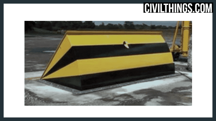
As discussed over, in the deployed placement, the wedge plate 16 offers to obstruct gain access to or traveling beyond the obstacle 10. The obstacle 10(e. g., the wedge plate 16 )may obstruct pedestrians or cars from accessing a property or pathway. If a vehicle is taking a trip in the direction of the released wedge plate 16(e. For instance, in one condition, the safety legs 86 might be prolonged throughoutmaintenance of the barrier visit the website 10.